key switch guide
This guide outlines the fundamentals of key switches, covering their purpose, basic operation, and why they matter in modern electronics. Readers will learn how switches convert mechanical motion into electrical signals, the typical construction, and key performance metrics to consider today.!
Types of Key Switches
Key switches come in various forms, primarily mechanical and membrane. Mechanical switches use physical contacts and offer tactile feedback, while membrane switches rely on flexible layers and are quieter. Each type suits different applications, balancing durability, cost, and feel. These distinctions guide choice!
Mechanical Switches
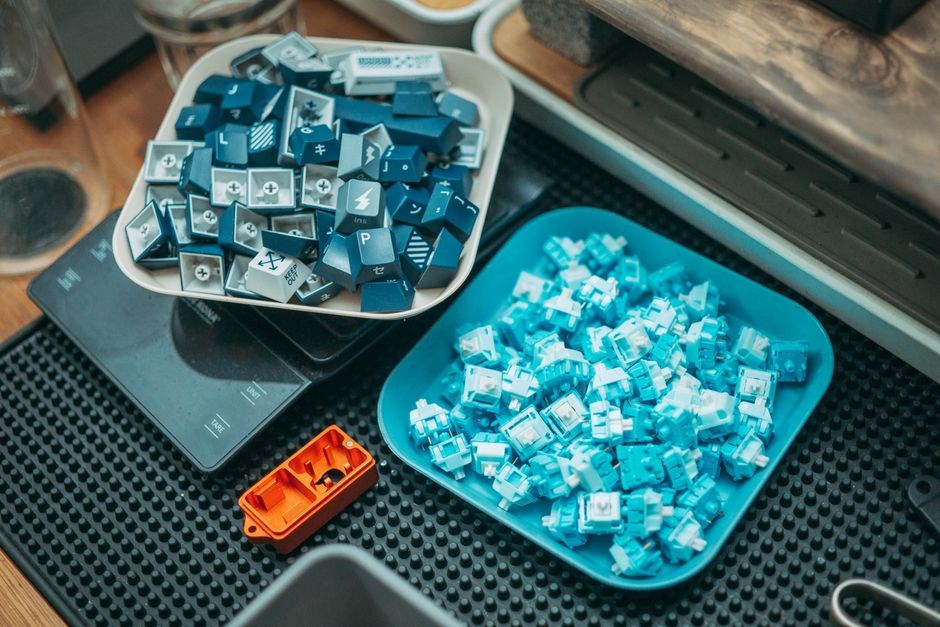
Mechanical switches form the core of many electronic interfaces, delivering tactile feedback through a physical contact mechanism. A key press moves a plunger that compresses a spring, forcing metal contacts together and completing a circuit; releasing the key lets the spring return the plunger, breaking the circuit. This simple yet robust design yields high durability, often rated for millions of actuations and resistance to temperature extremes.
Key variants include tactile switches, which give a noticeable bump and click; linear switches, offering smooth, uninterrupted motion; clicky switches, combining tactile feedback with an audible click; and adjustable‑force switches, allowing users to set the actuation pressure. Materials such as steel or brass contacts and silicone dampeners enhance longevity and noise control, while polycarbonate housings provide strength and environmental protection.
Because of their modular construction, mechanical switches can be swapped or upgraded without redesigning the entire system, making them ideal for both consumer devices and industrial applications where reliability and user feedback are paramount.
High‑grade steel or brass contacts provide excellent wear resistance, while silicone or rubber dampeners reduce noise and protect against shock. Polycarbonate or ABS housings offer strength and environmental protection, ensuring the switch can withstand temperature swings, humidity, and mechanical stress.
The modular design allows for easy replacement of individual keys or entire key arrays, reducing maintenance costs. In high‑traffic environments, this means a single faulty key can be swapped without shutting down the entire system, ensuring continuous operation and minimal downtime.
Mechanical switches are favored in keyboards, industrial panels, automotive controls, and gaming peripherals where tactile response and durability are critical. Their consistent performance and low failure rates make them suitable for both and mission‑critical applications.
Membrane Switches
Membrane switches use flexible layers of conductive ink or metal foil separated by an insulating spacer. When pressure is applied, the layers align, closing the circuit. This design eliminates moving parts, resulting in a very quiet, low‑profile, and cost‑effective solution suitable for touch panels, remote controls, and consumer electronics. Because the layers are bonded, the switch can be manufactured in large sheets and a bottom layer that completes the circuit when pressed. Because the layers are bonded, the switch can be manufactured quickly in large sheets and large‑scale production and then cut. The absence of metal contacts reduces the risk of corrosion and extends the life of the device in humid or dusty environments. However, membrane switches generally require a higher actuation force than mechanical counterparts and lack the tactile feedback that many users expect from a keyboard or button. They are also more susceptible to wear over time, as the conductive traces can degrade under repeated pressure. Despite these limitations, the low cost, thin profile, and ease of integration make membrane switches a popular choice for simple input devices, as well as household appliances, automotive dashboards, and industrial control panels where a tactile click is not essential. Their ability to be printed on flexible substrates also opens opportunities for wearable technology and foldable displays, where space constraints and durability are critical. In summary, membrane switches provide a lightweight, inexpensive, and reliable input method for applications that prioritize cost and form factor over tactile precision.
Key Switch Metrics
Key switch metrics evaluate performance: actuation force, travel distance, durability, noise level, and response time. Engineers compare these values to match application demands, ensuring reliable operation across temperature, humidity, and mechanical stress conditions. High speed. use!
Actuation Force
Actuation force is the pressure required to activate a key switch, measured in grams or newtons. It determines the tactile feel, typing speed, and fatigue level. Lower forces (30–40 g) enable rapid input for gaming, while higher forces (45–55 g) provide a deliberate, tactile experience favored by typists; Manufacturers calibrate force through spring tension, lever geometry, or magnetic attraction, ensuring consistency across thousands of switches. The force curve—linear, bump, or click—affects perceived effort; a tactile bump at 50 g signals actuation, reducing accidental double‑presses. Environmental factors such as temperature and humidity can shift force over time, so switches use materials that resist creep and maintain stable characteristics. Testing typically employs a force gauge, producing a force‑distance graph that visualizes the actuation point and total travel. Standardized rigs guarantee repeatability, allowing manufacturers to meet specified tolerances across batches. Users may fine‑tune force by adjusting spring stiffness or adding springs. Dynamic actuation force, measured during a press, can differ from static values due to vibration and friction. Advanced switches incorporate dampers or rubber domes to smooth the curve, reduce noise, and improve longevity. Material choice—stainless steel springs, silicone, polymer levers—affects magnitude and feel. Mechanical switches can achieve 30 g with a crisp bump; membrane switches often require 50–70 g. Optical or magnetic switches use alternative mechanisms for near‑zero‑bounce actuation, prized in gaming. Datasheets provide force curves, enabling side‑by‑side comparison. By analyzing these graphs, designers predict typing fatigue, key rollover, and ergonomics. A well‑chosen actuation force enhances user experience and extends switch life by reducing wear. Ultimately, actuation force is a core metric that blends mechanical design, material science, and ergonomics, guiding key switch selection and innovation. Choosing the right force ensures comfort, speed, and durability for any application; Engineers iterate on spring designs to fine‑tune the feel before finalizing a product. for optimal performance.

Travel Distance
Travel distance refers to the total linear movement of a key switch from its resting position to the point of actuation. It is measured in millimeters and influences typing speed, accuracy, and fatigue. Short travel (1.5–2.0 mm) allows rapid keystrokes with minimal finger movement, ideal for gaming and data entry. Longer travel (2.0–3.0 mm) offers a pronounced tactile feedback, reducing accidental presses and providing a typing experience writers and programmers. The actuation point is a subset of travel distance, typically occurring at 60–70 % of the total travel. Designers balance total travel with actuation distance to create switches that feel responsive yet comfortable. Mechanical switches often feature a lever arm that converts rotational motion into linear displacement, while membrane switches use a rubber dome that compresses. The lever’s geometry and spring tension determine the effective travel. Optical and magnetic switches employ a different mechanism, using a sensor that detects the key’s position, allowing for short travel (0.5–1.0 mm) while maintaining a crisp click. Variations in travel can affect key rollover and ghosting; shorter travel reduces the time keys remain pressed, improving performance. Environmental factors such as temperature can alter travel due to material expansion or contraction. Manufacturers provide travel specifications in datasheets, enabling users to compare switches side‑by‑side. Ergonomic studies show that moderate travel (1.8–2.2 mm) reduces finger strain over long sessions. Users can customize travel by adding or removing springs, or by selecting switches with lever stiffness. Ultimately, travel distance is a metric that shapes the tactile feel, speed, and ergonomics of a key switch, guiding both designers and end‑users in selecting the best fit their needs.!!!?
Choosing the Right Switch
Choosing the right switch depends on application, desired feel, and conditions. Evaluate typing speed, tactile feedback, actuation force, travel, and Match the switch type to your use case—gaming, office, or industrial—while considering temperature, dust, and vibration tolerance.
Application Needs
When selecting a key switch, the first consideration is the specific application that will drive its performance requirements. For high‑speed data entry or gaming, a switch with low actuation force and short travel is ideal, allowing rapid key presses while minimizing fatigue. In contrast, industrial control panels often demand rugged, high‑durability switches that can withstand harsh environments, including dust, moisture, and extreme temperatures. These switches typically feature sealed housings, high‑temperature ratings, and a robust mechanical design that resists wear over millions of cycles. For consumer electronics such as laptops or tablets, the focus shifts to a slim profile, quiet operation, and a smooth tactile feel that enhances user experience without compromising battery life. Additionally, the choice of switch can affect the device’s overall ergonomics; a tactile bump can provide visual feedback for users who rely on touch typing, while a linear switch offers a consistent feel that some users prefer for gaming or rapid typing. The application’s power budget plays a role: switches that consume less current are preferable for battery‑powered devices, while industrial systems can accommodate switches with higher current draw if needed. When evaluating switches for a specific use case, it is essential to balance tactile feedback, durability, and power consumption; a switch that feels satisfying to press can increase typing speed and reduce errors, while a robust design that resists dust and moisture ensures long‑term reliability in demanding environments. This careful assessment ensures optimal performance and longevity for all users
Environmental Factors
In selecting a key switch, environmental conditions dictate many design choices. Temperature extremes can cause plastic components to warp or metal contacts to oxidize, altering actuation force and reliability. Switches rated for high operation typically use heat‑resistant polymers and gold‑plated contacts to maintain conductivity. Humidity and moisture present another challenge; condensation can lead to corrosion or short circuits. Sealed or waterproof switches, often with IP ratings, protect internal contacts and maintain consistent performance in damp or marine settings. Dust and particulate ingress degrade switch life; filters or hermetic housings prevent abrasive particles from reaching the moving parts. In industrial or outdoor applications, vibration and shock tolerance are critical; ruggedized switches with reinforced housings and dampening materials resist mechanical fatigue. Electromagnetic interference (EMI) can affect signal integrity; shielded switches or those with grounded housings reduce noise. Finally, chemical exposure—such as solvents, acids, or alkalis—requires chemically resistant materials to avoid degradation. By evaluating these environmental factors, designers can choose switches that not only meet functional requirements but also endure the operational context, ensuring reliability and user satisfaction and durability!
Moreover, switch choice can influence power consumption in battery‑powered devices; low‑current switches extend battery life. The tactile feel matters for ergonomics; a distinct bump reduces typing errors. Extreme environments like aerospace or military equipment require switches meeting MIL‑STD‑810 or IEC 60068 for shock, vibration, and EMI. Consumer electronics favor quiet, slim linear or low‑force switches, yet they must resist dust ingress and maintain performance over many cycles. Matching a switch’s environmental specs to its intended use prevents failures and ensures durable, reliable products.
Installation Guide
Follow these steps: 1. Mount the switch plate, ensuring proper alignment. 2. Connect the leads to the PCB using solder or headers. 3. Test continuity with a multimeter before final assembly. 4. Secure the switch with screws, then verify operation.Check solder joints before final assembly
Hardware Setup
Begin by selecting a suitable mounting surface that can support the switch’s weight and provide a stable base. Clean the area with isopropyl alcohol to remove dust and oils, ensuring a strong bond for any adhesive or screws. Next, if the switch uses a plate, align it precisely with the mounting holes on the board. Use a small screwdriver or a precision drill to create pilot holes that match the screw size, avoiding over‑drilling which can weaken the board. For switches that require a gasket or spacer, insert the component carefully, checking that it sits flush with the plate to maintain consistent pressure on the contacts. When attaching the switch, apply a thin layer of epoxy or a suitable adhesive to the contact pads, allowing for a few minutes of curing time before proceeding. This step is critical for preventing electrical shorts and ensuring long‑term reliability. Once the adhesive has set, secure the switch with the appropriate screws, tightening them in a cross‑pattern to distribute force evenly. Verify that the switch’s mechanical travel is unobstructed and that the keycap can be seated without resistance. Finally, perform a continuity test using a multimeter set to the diode or continuity mode, checking each contact pair for proper electrical connection. If any contact shows an open circuit, re‑inspect the solder joints and adhesive placement. After confirming all connections, the switch is ready for software configuration and final integration into the device’s firmware. This systematic approach guarantees a robust installation that meets both performance and durability expectations. Done!!!!
Software Configuration
After the hardware is firmly in place, the next phase involves aligning firmware settings with the physical characteristics of the switch. Begin by identifying the microcontroller or firmware platform that will interpret the switch signals. Most modern boards use a bootloader that exposes a configuration interface, often via USB or UART. Connect the device to a host computer and launch the configuration utility. Within the utility, navigate to the “Key Mapping” section, where you can assign each switch to a specific action or keycode. For mechanical switches, you may also want to fine‑tune the debounce algorithm; a typical debounce window ranges from 5 to 20 milliseconds, depending on the switch’s mechanical noise profile. If the switch supports tactile or click feedback, enable the corresponding flags to ensure the firmware reports the correct event type. Some advanced firmware allows you to set a “tap‑to‑hold” threshold, which differentiates a short press from a long press. Adjust this threshold by testing the switch under typical usage conditions and recording the response time. Next, configure any power‑management settings. If the switch is part of a low‑power peripheral, enable “sleep‑on‑idle” to reduce current draw when the switch is not being pressed. Verify that the firmware correctly reports the switch’s state by using a serial monitor or a debugging tool that displays real‑time key events. Document.